
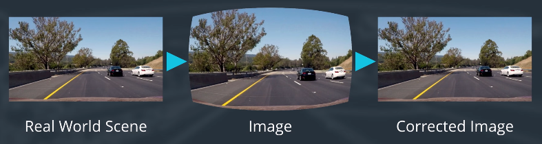
When we talk about camera calibration and Image distortion, we’re talking about what happens when a camera looks at 3D objects in the real world and transforms them into a 2D image. That transformation isn’t perfect.
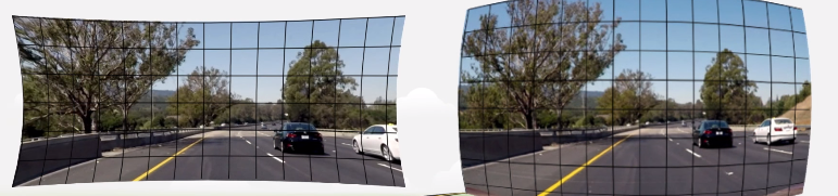
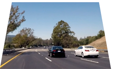
For example, here’s an image of a road and some images taken through the different camera lens that slightly distorted.
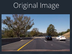
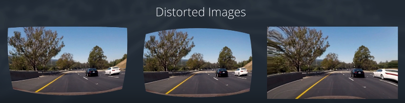
In these distorted images, you can see that the edges of the lanes are bent and sort of rounded or stretched outward. Our first step in analyzing camera is to undo this distortion so we can get correct and useful information out of them.
Why Distortion?
Before we get into the code and start correcting for distortion, let’s get some intuition as to how this distortion occurs.
Here’s a simple model of a camera called the pinhole camera model.
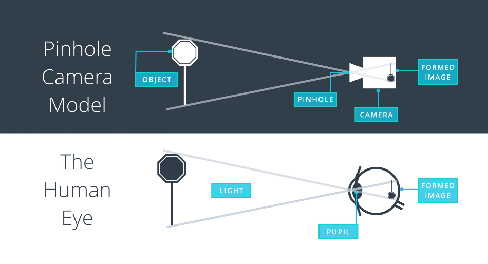
When a camera looking at an object, it is looking at the world similar to how our eyes do. By focusing the light that’s reflected off of objects in the world. In this case, though a small pinhole, the camera focuses the light that’s reflected off to a 3D traffic sign and forms a 2D image at the back of the camera.
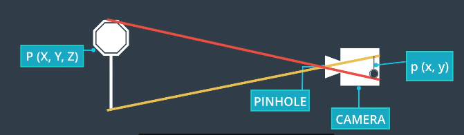
In math, the Transformation from 3D object points, P of X, Y and Z to X and Y is done by a transformative matrix called the camera matrix(C), we’ll be using this to calibrate the camera.
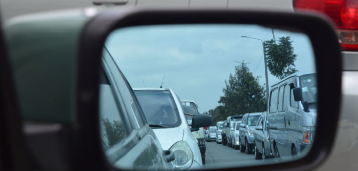
However, real cameras don’t use tiny pinholes; they use lenses to focus on multiple light rays at a time which allows them to quickly form images. But, lenses can introduce distortion too.
Light lays often bend a little too much at the edges of a curved lens of a camera, and this creates the effect that distorts the edges of the images.
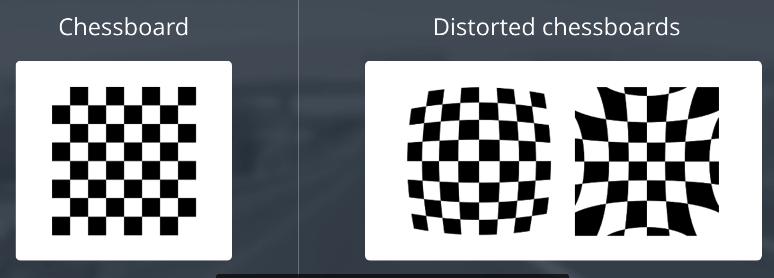
Types of Distortion
Radial Distortion: Radial Distortion is the most common type that affects the images, In which when a camera captured pictures of straight lines appeared slightly curved or bent
Tangential distortion: Tangential distortion occurs mainly because the lens is not parallely aligned to the imaging plane, that makes the image to be extended a little while longer or tilted, it makes the objects appear farther away or even closer than they actually are.
So, In order to reduce the distortion, luckily this distortion can be captured by five numbers called Distortion Coefficients, whose values reflect the amount of radial and tangential distortion in an image.

If we know the values of all the coefficients, we can use them to calibrate our camera and undistort the distorted images.
Measuring Distortion
So, we know that the distortion changes the size and shape of the object in an image. But, how do we calibrate for that?
Well, we can take pictures of known shapes, then we’ll be able to detect and correct any distortion errors. We could choose any shape to calibrate our camera, and we’ll use a chessboard.
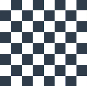
A chessboard is great for calibration because it's regular, high contrast pattern makes it easy to detect automatically. And we know how an undistorted flat chessboard looks like. So, if we use our camera to take pictures of Chessboard at different angles
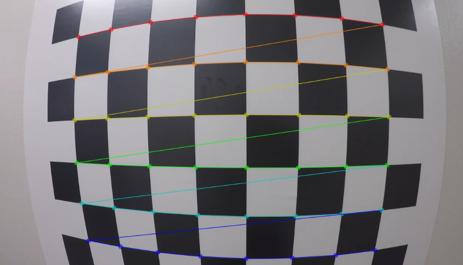
Finding Corners
Open CV helps to automatically detect the corners and draw on it by findChessboardCorners() and drawChessboardCorners()
Applying both functions to a sample image, results:
import numpy as np
import cv2
import matplotlib.pyplot as plt
import matplotlib.image as mpimg
# prepare object points
nx = 8 number of inside corners in x
ny = 6 number of inside corners in y
# Make a list of calibration images
fname = 'calibration_test.png'
img = cv2.imread(fname)
# Convert to grayscale
gray = cv2.cvtColor(img, cv2.COLOR_BGR2GRAY)
# Find the chessboard corners
ret, corners = cv2.findChessboardCorners(gray, (nx, ny), None)
# If found, draw corners
if ret == True:
    # Draw and display the corners
    cv2.drawChessboardCorners(img, (nx, ny), corners, ret)
    plt.imshow(img)
Calibrating The Camera
In order to Calibrate the camera, the first step will be to read in calibration Images of a chess board. It’s recommended to use at least 20 images to get a reliable calibration, For this, we have a lot of images here, each chess board has eight by six corners to detect,
To calibrate a camera, OpenCV gives us the calibrateCamera() function
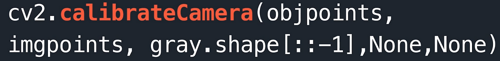
This takes in Object points, Image points[will understand these points in a moment], and the shape of the image and using these inputs, it calculates and returns
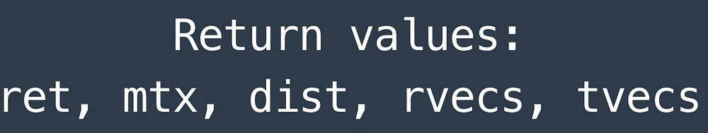
mtx: Camera Matrix, which helps to transform 3D objects points to 2D image points.
dist: distortion coefficient
It also returns the position of the camera in the world, with the values of rotation and translation vectors rvecs, tvecs
The next function that we require is undistort().
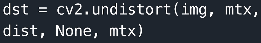
The undistort function takes in a distorted image, our camera matrix, and distortion coefficients and it returns an undistorted, often called destination image.
In calibrateCamera() function we need object points and image points.
import numpy as np
import cv2
import matplotlib.pyplot as plt
import matplotlib.image as mpimg
#read in a calibration image
img = mpimg.imread('../calibration_images/calibration1.jpg')
plt.imshow(img)
First, Done with numpy, openCV, and plotting imports, then we are gonna read the first image calibarion1.jpg and display it.
Now, we are gonna map the coordinates of the corners in the 2D displayed image which called as imagepoints , to the 3D coordinates of the real, undistorted chessboard corners, which are called as objectpoinst.
So, we are gonna set up two empty arrays to hold these points, objectpoints and imagepoints
# Arrays to store object points and image points from all the images
objpoints = [] # 3D points in real world space
imgpoints = [] # 2D points in image plane
The object points will all be the same, just the known object corners of the chess board corners for an eight by six board.
So, we are going to prepare these object points, first by creating six by eight points in an array, each with three columns for the x,y and z coordinates of each corner. We will then initialize all these to 0s using Numpy’s zeros function. The z coordinates will stay zero so leave that as it is but, for our first two columns x and y, use Numpy’s mgrid function to generate the coordinates that we want. mgrid returns the coordinate values for given grid size and shape those coordinates back into two columns, one for x and one for y:
# Prepare obj points, like (0, 0, 0), (1, 0, 0), (2, 0, 0)....., (7, 5, 0)
objp = np.zeros((6*8,3), np.float32)
objp[:,:,] =  mp.mgrid[0:8,0:6].T.reshape(-1,2) # x,y coordinates
Next to create the imagepoints, we need to consider the distorted calibrated image and detect the corners of the board. OpenCV gives us an easy way to detect chessboard corners with a function called findChessboardCorners(), that returns the corners found in a grayscale image.
So, we will convert the image to greyscale and then pass that to the findChessboardCorners() function. This function takes in a grayscle image along with the dimensions of the chess board corners. In this case 8 by 6 and last parameter is for any flags; there are none in this example:
# Convert image to grayscale
gray = cv2.cvtColor(img, cv2.COLOR_BRG2GRAY)
# Find the Chesse board corners
rer, corners = cv2.findChessboardCorners(gray, (8,6), None)
If this function detects corners, we are gonna append those points to the image points array and also add our prepared object points objp to the objectpoints array. These object points will be the same for all of the calibration images since they represent a real chessboard.
# If corners are found, add object points, image points
if ret == True:
    imgpoints.append(corners)
    objpoints.append(objp)
Next, we also draw the detected corners, with a call to drawChessboardCorners() , that takes in our image, corner dimensions and corner points.
# If corners are found, add object points, image points
if ret == True:
    imgpoints.append(corners)
    objpoints.append(objp)

    # Draw and display the corners
    img = cv2.drawChessboardCorners(img, (8,6), corners, ret)
    plt.imshow(img)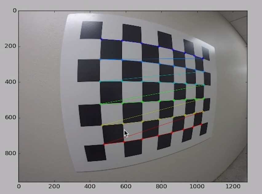
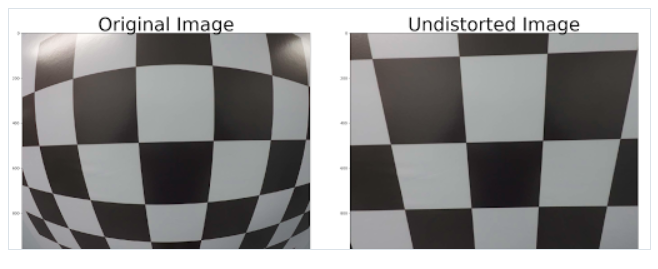
Correction for Distortion
import pickle
import cv2
import numpy as np
import matplotlib.pyplot as plt
import matplotlib.image as mpimg
# Read in the saved objpoints and imgpoints
dist_pickle = pickle.load( open( "wide_dist_pickle.p", "rb" ) )
objpoints = dist_pickle["objpoints"]
imgpoints = dist_pickle["imgpoints"]
# Read in an image
img = cv2.imread('test_image.png')
def cal_undistort(img, objpoints, imgpoints):
    ret, mtx, dist, rvecs, tvecs = cv2.calibrateCamera(objpoints, imgpoints, img.shape[1:], None, None)
    undist = cv2.undistort(img, mtx, dist, None, mtx)
    return undist
undistorted = cal_undistort(img, objpoints, imgpoints)
f, (ax1, ax2) = plt.subplots(1, 2, figsize=(24, 9))
f.tight_layout()
ax1.imshow(img)
ax1.set_title('Original Image', fontsize=50)
ax2.imshow(undistorted)
ax2.set_title('Undistorted Image', fontsize=50)
plt.subplots_adjust(left=0., right=1, top=0.9, bottom=0.)
Get distortion pickle file and test image
Output result:

Reference: Udacity Self Driving Car Engineer Nanodegree
Originally Published at: Analytics Vidhya